February Parts Special - Order Through Shop.Deere.Com

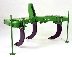
 913 V-Ripper
The frame design of the 913 V-Ripper positions the standards in a V pattern:
The 127-mm x 178-mm (5-in. x 7-in.) cross-section frame has 10-mm (3/8-in.) thick walls:
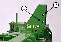
 Low and high positions on 3-point mast
3-point hitch hookup is for Category 2 or 3N tractors.
The integral hitch can be set to two positions:
 Soil probe
The soil probe helps operators to determine the proper operating depth of their ripper points,
38 mm (1.5 in.) below the bottom of the compaction layer.
The probe allows obtaining the maximum amount of soil fracturing from the entire family of John Deere ripper points. Marked in 51-mm (2-in.) increments from 254 mm to 559 mm (10 in. to 22 in.), the probe provides accurate feedback of compaction layer depth.
It is stored on the mainframe of the ripper for convenient access. The operator's manual explains the proper use of the soil probe.
| Key Specs | 913-v-ripper Current Model |
|---|---|
| Working width | Option 1: 2.5 m 8.33 ft Option 2: 3.2 m 10.42 ft Option 3: 3.8 m 12.5 ft |
| Transport width | Option 1: 2.1 m 7 ft Option 2: 2.1 m Option 3: 2.1 m |
| Operating depth | Maximum 58.4 cm 23 in. |
| Miles per hour | |
| Horsepower per standard | |
| Spacings | 50.8 cm 20 in. 63.5 cm 25 in. 76.2 cm 30 in. |
| Tool configuration | |
| Type | V-ripper |
| Option 1 | Standard: 3, spacing: 50.8 cm 20 in. |
| Option 2 | Standard: 3, spacing: 63.5 cm 25 in. |
| Option 3 | Standard: 3, spacing: 76.2 cm 30 in. |
| Option 4 | |
| Option 5 | |
| Option 6 | |
| Option 7 | |
| Option 8 | |
| Option 9 | |
| Option 10 | |
| Option 11 | |
| Option 12 | |
| Option 13 | |
| Option 14 | |
| Option 15 | |
| Option 16 | |
| Option 17 | |
| Option 18 | |
| Option 19 | |
| Option 20 | |
| Option 21 | |
| Option 22 | |
| Working width | |
| Option 1 | 2.5 m 8.33 ft |
| Option 2 | 3.2 m 10.42 ft |
| Option 3 | 3.8 m 12.5 ft |
| Option 4 | |
| Option 5 | |
| Option 6 | |
| Option 7 | |
| Option 8 | |
| Option 9 | |
| Option 10 | |
| Option 11 | |
| Option 12 | |
| Option 13 | |
| Option 14 | |
| Option 15 | |
| Option 16 | |
| Option 17 | |
| Option 18 | |
| Option 19 | |
| Option 20 | |
| Option 21 | |
| Option 22 | |
| Transport width | |
| Option 1 | 2.1 m 7 ft |
| Option 2 | 2.1 m 7 ft |
| Option 3 | 2.1 m 7 ft |
| Option 4 | |
| Option 5 | |
| Option 6 | |
| Option 7 | |
| Option 8 | |
| Option 9 | |
| Option 10 | |
| Option 11 | |
| Option 12 | |
| Option 13 | |
| Option 14 | |
| Option 15 | |
| Option 16 | |
| Option 17 | |
| Option 18 | |
| Option 19 | |
| Option 20 | |
| Option 21 | |
| Option 22 | |
| Operating depth | |
| Maximum | 58.4 cm 23 in. |
| Frame | |
| Size | |
| Maximum underframe clearance | |
| Operating speed | |
| Miles per hour | |
| Horsepower required | |
| Horsepower per standard | |
| Depth control | |
| Option 1 | Intergral units are controlled by tractor, rockshaft, and gauge wheels |
| Option 2 | |
| Option 3 | |
| Hydraulic requirements | |
| Option 1 | |
| Option 2 | |
| Hitch | |
| Options | Integral |
| Three-point hitch requirements | Category 2 or 3N with Quik Coupler Category 3N without Quik Coupler |
| Pull-type description | |
| Standard options | |
| Spacings | 50.8 cm 20 in. 63.5 cm 25 in. 76.2 cm 30 in. |
| Option 1 | Trip force 5,443 kg 12,000 lb Standard type Straight or parabolic with wear shin Shear-bolt |
| Option 2 | Trip force 2,540 kg 5,600 lb Standard type Straight with wear shin or parabolic Safety-trip |
| Option 3 | Trip force 2,404 kg 5,300 lb Standard type Straight with wear shin or parabolic Cushion-trip |
| Option 4 | Trip force 1,451.5 to 2,404 kg 3,200 to 5,300 lb Standard type Parabolic Spring-reset rock standard |
| Coulters | |
| Description | |
| Type | |
| Pounds of force | |
| Blades | |
| Closing wheel attachment | |
| Description | |
| Down force | |
| Size | |
| Spacing | |
| Angle adjustments | |
| Stabilizer/gauge wheels | |
| Type | |
| Wheels | |
| Tires | |
| Pull-type wheels | |
| Description | |
| Additional feature | |
| Option 1 | |
| Option 2 | |
| Option 3 | |
| Option 4 | |
| Ground-engaging components | |
| Options |
© COPYRIGHT 2025 LEGACY EQUIPMENT - ALL RIGHTS RESERVED| Privacy Policy | Powered By